SORPTIVITY CHARACTERISTICS OF HIGH PERFORMANCE MORTAR MIXES USING FLY ASH AND BLAST FURNACE SLAG
BNVVS Sundara Rao*** V Ravindra* V.S. Chalapathi Rao**
*Associate Professor in civil Engg., JNTU College of Engg., Kakinada,
**Head of Civil Engg., Section, D.A. Government Polytechnic, Ongole.
***Chief Consultant, Sundar Associates, Kakinada.ABSTRACT
The rich mortar mixes with increased compressive strength and enhanced durability characteristics are termed as High Performance mortars (HPM). The Sorptivity is an easily measurable material property which characterizes the tendency of a porous material to absorb and transmit water by capillarity and is based on the unsaturated flow theory. An experimental investigation was done to study the Sorptivity characteristics of a HPM using (i) fly ash and super plasticizer in rich mortar mix (1:1.5/0.35) and (ii) slag and super plasticizer in rich mortar mix (1:2/0.37), using two grades of cement (43 & 53). The results of Sorptivity at the end of 3,7 and 28 days of curing are presented. It has been concluded from the study that the addition of fly ash or slag and super plasticizer has improved the Sorptivity with increase in age of curing and grade of cement.
INTRODUCTION
The significance of the studies on cement mortar need not be emphasized as it forms an important component of cement concrete and the cement mortar itself is a structural material in many applications such as production of Ferro cement elements, repair of deteriorated RCC structures and strengthening of structural components using jacketing techniques. Improving the performance aspects of cement mortar significantly enhances the durability properties in many applications of cement concrete. One of the means of achieving high performance is by the use of pozzolanic admixtures such as fly ash and blast furnace slag with the super plasticizers by which the pore structure can be modified. The fly ash or slag and super plasticizers have a great role to play in the process of modifying the pore structure and thereby reducing the shrinkage and Sorptivity to a great extent.
A cement mortar with a low water cement ratio and consequent high strength can be termed as high strength mortar (HSM). Due to the advent of high performance concrete (HPC) technology, it is now possible to improve the performance of HSM. The improvement can be done by reducing comparatively both cement and water contents. While the HSM can be achieved by incorporating pozzolanic admixtures, such as fly ash, ground granulated blasé furnace slag powder and silica fume, the latter is achieved by using chemical admixtures such as super plasticizer. Such cement mortars are found to have higher strengths and superior durability characteristics and can therefore be called as high performance cement mortars (HPM).
Sorptivity is a material property which characterizes the tendency of a porous material to absorb and transmit water by capillarity. The cumulative water absorption (per unit area of the inflow surface) increases as the square root of the elapsed time, ‘T’.
I = S.t½, therefore S= I / t½,WhereS = Sorptivity in mm “minT = elapsed time in minutes.I = “W/ AdW = increase in weight.A = surface area of specimen through which water penetrated (mm2)d = density of waterThe aim of the present investigation is to study the performance characteristic of Sorptivity of high performance mortar.
EXPERIMENTAL INVESTIGATION
The work was carried out in two groups, viz.,
(i) using fly ash with & without super plasticizer and
(ii) using slag with & without super plasticizer.
Mix proportions of 1:1.5/0.35 and 1:2/0.37 were selected from the point of view of strength and flow ability. Two grades of cement (43 grade and 53 grade) were used to conduct the tests. From the point of view of reduction in permeability with the increase fly ash/slag content, for this study the fly ash/slag content is fixed as 20% of partial replacement of cement. The dosage of super plasticizer was fixed as 20 ml per bag of cement, the work is divided into four stages for each of the above two groups.
Stage – I: without fly ash/ (slag) and without super plasticizer.
Stage – II: without fly ash/ (slag) and with super plasticizer.
Stage -III: with fly ash/ (slag) and without super plasticizer.
Stage -IV: with fly ash/ (slag) and with super plasticizer.
In all the four stages the specimens were cast for testing Sorptivity using the above said mix proportion for each of the two grades of cement (43 & 53). For all the four stages the specimens were cast in 8 batches for each group with 6 specimens in each batch. The size of the cylindrical specimen used is 50mm diameter and 100mm height as per the test conducted by Hall (1989).
Materials used
Cement: two grades of cement, 43 grade conforming to IS 8112 with specific gravity 2.88 and 53 grade conforming to IS 12269 with specific gravity 3.16. .
Aggregate: Locally available river sand conforming to IS 650-1991, passing through 1.18mm sieve with a specific gravity of 2.4.
Water: Potable water was used for mixing and curing purpose. FI!’y mire Obtained from VTPS, Vijayawada, having specific gravity 2.18.
Slag: The B.F. Slag used in this investigation was obtained from VISHAKAPATNAM STEEL PLANT, VISAKHAPATNAM.
Superplasticizer: By trade name Plaxem’ conforming to IS 9103-1979 with a recommended dosage of 20m1 per bag of cement.
Casting and curing: Cylindrical specimens were cast in split moulds of 50mm internal diameter and 100mm height. This mould is placed on a non-porous plate firmly held manually to prevent dislocation. The inner surface of the mould is smeared by lubricating oil. The cement mortar prepared was placed in the mould and compacted. After casting the moulds were placed under moist gunny bags for 24 hours and then the mould was opened to remove the specimen. All the specimens were immersed in curing tank and cured for specified number of days i.e., 3, 7 and 28 days.
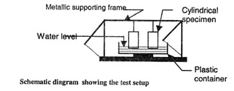
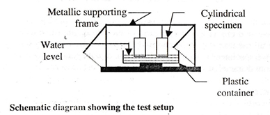
Test procedure: The Sorptivity can be determined by the measurement of the capillary rise absorption rate on reasonably homogeneous material. Water was used as the test fluid. The specimens are suspended as shown in the schematic diagram with the water level not more than 5mm above the base of the specimen and the flow from the peripheral surface is prevented by .sealing it properly with nonabsorbent coating. The quantity of water absorbed in a time period of 30 minutes was measured by weighing the specimen on a top pan balance weighing up to 0.1& Surface water on the specimen was wiped off with a dampened tissue and each weighing operation was completed within 30 seconds.
RESULTS AND DISCUSSIONS
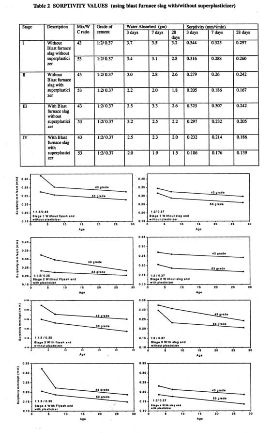
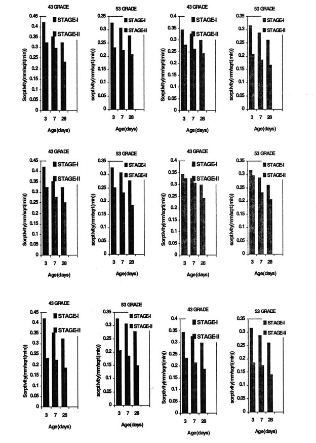
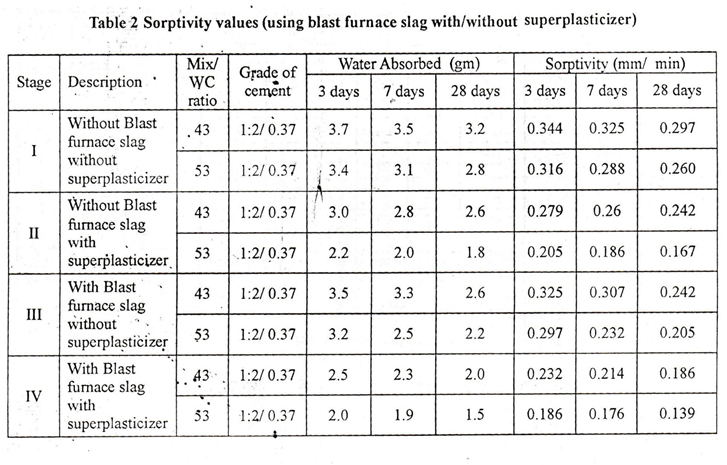
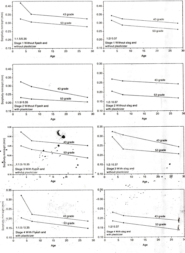
The experimental results are presented in the table and shown in figures.
EFFECT OF AGE AND GRADE OF CEMENT ON WATER SORPTIVITY
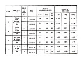
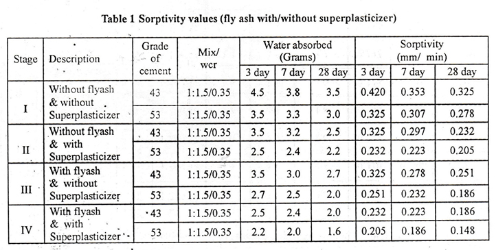
It is observed that there is a general decrease in Sorptivity for mortars with / without fly ash (or slag) and with / without super plasticizer with the increase in age and grade of cement. Based on the experimental results it is observed that 53 grade cement reported a better Sorptivity (low absorption).
EFFECT OF SUPERPLASTICIZER ON WATER SORPTIVITY
From table and figures it can be observed that there is a decrease in Sorptivity with addition of supeiplasticizer for both the grades of cement. The reason may be that as the super plasticizer used is a workability agent the absorption of water (Sorptivity) may not be much. A Sorptivity value of 0.205 mmrmin using 53 grade cement was obtained as against 0.232 mm / ” min using 43 grade cement with C.M 1:1.5/0.35 and 0.167 mm/”min using 53 grade was obtained as against 0.242 rnmf’min using 43 grade with C.M 1:2/(0.37).
EFFECT OF FLY ASH ON WATER SORPTIVITY
From table and figures it can be observed that there is a decrease in Sorptivity with partial replacement of cement by 20% fly ash for both the grades of cement used. The decrease is however more with partial replacement of cement by 20% fly ash as compared to the addition of super plasticizer in case of 53 grade cement fig (9) and the decrease is less in case of 43 grade cement fig (8). The decrease may be due to pozzolanic action. A Sorptivity value of 0186 mm / “min using 53 grade cement was obtained as against 0.251 mm / “min using 43 grade cement.
EFFECT OF BLAST FURNACE SLAG ON WATER. SORPTIVITY
Same trend as in the case of using fly ash is observed. A Sorptivity value of 0.205 mm / “min using 53 grade cement was obtained as against 0242 mm / “min using 43 grade cement.
COMBINED EFFECT OF FLY ASH (OR BLAST FURNACE SLAG) AND SUPERP/ i.ASTICIZER ON WATER SORPTIVITY
From table and figure (4) it is evident that there is a general decrease in Sorptivity values irrespective of grade of cement. The average decrease of Sorptivity is 42% for 43 grade cement and 46% for 53 grade cement using fly ash and 37% for 43 grade cement and 46.50% for 53 grade cement using blast furnace slag. The minimum value of Sorptivity was reported for 53 grade cement which is equal. to 0139 mm I “min using, fly ash and 0.148 mm / “min using blast furnace slag.
CONCLUSIONS
1. A decrease in Sorptivity is observed with the increase of age and grade of cement for plain cement mortars. i.e., with / without fly ash (or blast furnace slag) and with / without super plasticizer.
2. A decrease in Sorptivity is observed with addition of either superplasticizer (or) fly ash (or) blast furnace slag with both the grades of cements.
3. The decrease in Sorptivity with partial replacement of cement by 20% fly ash as compared to the addition of superplasticizer is more in case of 53 grade cement and less in case of 43 grade cement.
4. The decrease in Sorptivity with addition of superplasticizer is more than the decrease in Sorptivity with partial replacement of cement by 20% blast furnace slag in case of 53 grade cement and almost. same in case of 43 grade cement.
5. For the same quantity of replacement of cement by fly ash or blast furnace slag and for the same dosage of superplasticizer, 53 grade cement mortar reported lesser Sorptivity as compared to 43 grade cement mortar. The percentage decrease in Sorptivity is 42% with 43 grade cement and 46% with 53 grade cement using fly ash and 37% and 46.5% with 43 grade and 53 grade cements respectively using blast furnace slag.
GGBS-ITS PRODUCTION, COMPOSITIONS AND INVESTIGATIONS ON CONCRETE-A REVIEW
S.K.Sekar’ VRavichandran2
1-Associate Professor of Civil Engineering,Vellore Institute of Technology, vellore
‘Assistant Professor of Civil Engineering,C.Abdul Hakeem College of Engineering & Technology, Mel visharam.ABSTRACT
Blast furnace slag is a black colored non-metallic product consisting of silicates and aluminium silicates of calcium derived from the blast furnace in the production of iron from ore at a temperature of 1600°C. Ground Granulated Blast furnace Slag (GGBS) can be obtained after grinding the blast furnace slag. This paper reviews the production and compositions of GGBS and the investigations on concrete while it is partially incorporated in the place of Ordinary Portland Cement (OPC). The chemical compositions of GGBS have a great effect on the mechanical and durability properties of concrete. Its high basicity can cause cementing property. This makes the possibility to design GGBS concrete for a desired strength at any given percentage of replacement. Also the use of GGBS in the concrete results in some advantages over conventional concrete. Therefore, the use of GGBS as a cementing component should be given a priority from technical, economical and environmental considerations.
Key Words: Ground Granulated Blast Furnace Slag, Ordinary Portland cement, Scanning Electron Microscope
INTRODUCTION
Nowadays, the utilisation of GGBS in concrete as a partial replacement of {PC is well established. Depending upon the GGBS content, the long-term strength and durability of concrete containing GOBS exceeds that of normal plain cement concrete. The development of the strength was slow during the first 28 days of hydration for concrete containing 40-65% GGBS as OPC replacement. However, after 28 days of hydration, the strength of GGI3S concrete was higher than that of normal concrete especially at 40 % replacement. The slight variation in the results are mainly depending upon the chemical composition and the fineness of GGBS.The hydration product of Ca(OH)2 activates the slag hydration from a mixture of low CaO/Si02 and CaO-Si 02_H2O(C-S-H). The permeability and penetration of chloride ions in GGBS specimens are prominently reduced in mortar test. The modified microstructure of cementitious paste which has more capillary pores filled with low density C-S-H gel than normal Portland Cement Paste.
It is observed that GGBS can be effectively used to reduce the pore size and cumulative pore volume considerably. The investigations on mechanical and durability properties are reviewed as under by the partial replacement of GGBS with OPC.
PRODUCTION OF GGBS
GGBS is a by-product from the conversion of iron-ore into iron in a blast furnace. The typical diagram and main parts of blast furnace is shown in the Fig. I. The elements of blast furnace are Hearth (lower section), Bosh (middle section) and Stack&Charging mechanism (upper section). Generally the blast furnace is charged in such a way that ore, flux and coke are deposited in alternative layers in the proportions as required by the operation, The iron ore processed in blast furnaces is usually in the form of an oxide either hematite (Fe203) or magnetite (Fe.04), Limestone or dolomite acts as a flux in iron smelting. Limestone decomposes into lime and carbon monoxide and the lime reacts with the silicious impurities in the ore and coke ash to form a fusible slag. The air is preheated to about 1000°C in the heaters attached to the furnace and then blown in through tuyers (vents) spaced around the furnace near its lower end. The action of preheated air and carbon monoxide with limestone forms molten iron from the ore, which is collected at the bottom of the furnace, The lime with impurities in the ore to form slag consisting mainly of calcium aluminium silicate, which floats at the top of molten iron in the blast furnace. The molten iron and slag are tapped out separately from the blast furnace. The temperature inside the furnace is about 1600°C during the extraction of iron (pig) from iron ore. At about 800°C,the limestone begins to decompose and is completely decomposed at 1000°C, forming the slag. The approximate quantities of materials in both charge and product of a blast furnace is given in Table 1.
Above table clearly indicates that the quantity of slag from iron manufacturing industry is very high. After tapping doe slag from furnace, it is ground for the specific surface area of about 390 m2/kg on par with the specific surface area of OPC.
COMPOSITION AND PROPERTIES OF OPC AND GGBS
The chemical composition and properties of OPC and GGBS are given in Table 2. This table shows that the major chemical composition of GGBS is approximately closer to the composition of OPC. Since the binding component (CaO) of GOBS is about 43%, it may be used for making concrete with the partial replacement of OPC. The other major composition of GGBS is Si02, which is slightly more than the percentage of OPC.This increase in quantity may not affect much on the property of concrete while making it by GOBS and OPC. The percentages of other chemical compositions like A1,03, FeO,,, MgO, etc also slightly vary. Therefore, the properties of concrete made by GGBS and OPC may not have much variation with respect to conventional concrete. Thus the property study is necessary while GGBS is partially repined by OPC for making of concrete.
National Seminar on Detailing of R.0 & Steel Structures.
Madras, 22 – 23rd December 1989DETAILING OF CANTILEVER SLABS AND BEAMS
BADAM SUNDARA RAO
M/s Sundar Associates, Basement Floor, 27-9-52,
Pulavarti Street. KAKINADA – 533 001.ABSTRACT
Detailing needs proper attention for R.C.C. Structures and Steel Structures. But the actual problem is that many structural engineers are very good designers who can design very well but may not be good in detailing. Detailing is in between Design and Construction. Design is a concept and Detailing is a language of communication and the structure is the outcome. Detailing means exact placement of reinforcing steel at the desired places with the required spacing in the required profile. Reinforcement detailing lays a vital role in the efficiency of the structure, particularly in case of cantilevers. Many failures in cantilever slabs have been observed. The main cause of these failures is due to improper placement of steel, i.e., due to lack of proper Detailing. The designer should prepare proper working drawings giving all the necessary details so that field engineers can execute the work with high efficiency.
COMMON MISTAKES IN DESIGN OF CANTILEVERS
The causes of most common mistakes in the design and detailing cantilevers are
1. Counter weight
2. Calculation of loads
3. Span to depth ratio
4. Torsion in beams
5. Length of encasement and anchorage length
These are discussed below.
Counter weight: When a cantilever is proposed to be laid. First and foremost, a check has to be made for proper counter weight. For this, masonry wall of adequate weight should be constructed before removing the props. Careful instruction should be given in this regard, as otherwise the structure may damage badly. Check for local crushing of brick masonry should be done. The beams over windows or openings should not be stopped but should be continued over a solid wall to avoid local crashing.
Calculation of loads: The live load on cantilever is more than that of any other floor area. IS 875 (Part2 – Imposed loads)-1987, suggests a live load of 3 KN/m2 for class 200 loading and for all other cases alive load of 4 KN/m2 is suggested in case of Balconies not liable to overcrowding and in case of overcrowding, a minimum live load of 4 1\1\7″ Tim’ is suggested. Thus, Proper care has to be exercised while selecting the loads on balconies. Corridors often serve several occupancies and are used for transporting furniture and goods. The weight of parapet/drop wall are also to be carefully calculated and accounted for in the design.
Span to Depth Ratio: For cantilevers, the basic value of span to effective depth ratio for spans upto 10m, as per IS 456-1978 (See art.22.2.i) is 7 and for the spans above 10m, detailed deflection calculations should be done. The basic value is to be modified depending on the type of steel used for tension reinforcement.
Torsion in beams: The beams supporting the cantilever slabs should be carefully checked for Torsion. The design of beam should be checked for torsion as per the provision of IS 456. The IS code suggests the following formulae for calculating the reinforcement. (Ref. art. 48.4)Reinforcement for torsion, when required, shall consist of longitudinal and transverse reinforcement.
Longitudinal reinforcement
The longitudinal reinforcement shall be designed to resist an equivalent bending moment, Me1, given by Me1 = M+Mt
Where M = Bending moment at the cross section, and
M = T(1 + D/b)/1.70
Where T is the torsional moment, D is the overall depth of the beam and b is the breadth of the beam.
If the numerical value of Mt, as defined above exceeds the numerical value of Moment M, longitudinal reinforcement shall be provided on the flexural compression face, such that the beam can also withstand an equivalent moment Me2 given by Me2 = Mt – M, the moment being taken as acting in the opposite sense to the moment M.
Transverse reinforcement
Two legged closed hoops enclosing the corner longitudinal bars shall have an area of cross section Asv, given by (See also Fig.1)
Where T = Torsional Moment, V = Shear Force, Sv = Spacing of stirrup reinforcement,
b1 = C/c distance between corner bars in the direction of width,
d1 = C/c distance between corner bars in the direction of depth,
b = Breadth of Member, αSv = Permissible tensile stress in shear reinforcement,
πVe = Equivalent shear stress and πc = Shear strength of concrete
Length of Encasement and Anchorage Length: lack of counter-balancing steel or load leads to failures. Detailed calculations are always quite good but the thumb rule which can successfully be used is “Provide an encasement length of 1.50 times the length of a cantilever in inner slab or beam or column if adequate counter balancing provisions are not available. The factor of safety against overturning must not be less than 2.
Detailing of corner reinforcement: The detailing of corner reinforcement needs careful attention. Many failures have occurred at corners only. Cantilever action in two directions is to be considered. Provide fan reinforcement with usual precautions (See Fig.2).
Positioning of chairs while placement of reinforcement:
The positioning of chairs should be carefully indicated and the following points are to be kept in view.1. Provide reinforcement chair to keep reinforcement in correct position.
2. Reinforcement must be kept at the designed level of placement.
During concreting if chairs are not provided below the top reinforcement (to maintain it as the top of the slab), steel sags down to mid depth or even lower. On removal of centering the chajja comes down. In some cases it ma]’ come down later due to creep effect and due to the steel being at a level below the designed position. The top of support cracks due to tension. Creep deformation of concrete starts. When the crack extends lower. the chaija comes down.
A typical arrangement of chairs is should in Fig.3.
General notes on cantilevers
a. In case of large cantilevers, while designing, special care is to be exercised with regard to check for deflection, check for bending moment, check for long term effects viz., plastic flow, creep, fatigue, check for anchorage, check for counterweight etc.
b. While executing large cantilevers, an upward rise (camber) of 3mm per meter span of cantilever or about double the calculated dead load deflection is best preferred to avoid the creep effects of deflection.
c. Concreting of cantilever must not be started without ensuring counter-balancing arrange-ments.
SUMMARY AND CONCLUSIONS
The detailing of cantilever slabs and beams are discussed. Such beams and slabs are often encountered in practice but very little precautions are taken while executing them. The common mistakes that are done are highlighted and suggestions are given. These suggestions if followed will result in good detailing and ultimately in safe and sound cantilever slabs and beams.
SLURRY INFILTRATED FIBROUS REINFORCED CONCRETE (SIFCON)
GENERAL
Slurry Infiltrated Fibrous Reinforced Concrete ‘(SIFCON) is a relatively new high performance and advanced material and can be considered as a special type of Steel Fiber Reinforced Concrete (SFRC).The technique of infiltrated layers of steel fibers with Portland cement based materials was first proposed by Haynes (1968). Lankard (1979) modified the method used by Haynes and proved that if percentage of steel fibers in cement matrix could be increased, one could get a material with very high strength properties which he christened as SIFCON.
WHAT IS SIFCON?
SIFCON is unique construction material possessing high strength as well as large ductility and far excellent potential for structural applications when accidental (or) abnormal loads are encountered during services SIFCON also exhibit new behavioral phenomenon, that of “Fiber lock” which believed to be responsible for its outstanding stress-strain properties. The matrix in SIFCON has no coarse aggregates, but a high cementations content. However, it may contain fine (or) coarse sand and additives such as fly ash, micro silica and latex emulsions. The matrix fineness must be designed so as to properly infiltrate the fiber network placed in moulds, since otherwise, large pores may form leading to substantial reduction in properties. A controlled quantity of high range water reducing admixtures (super plasticizer) may be used for improving flowing characteristics of SIFCON. All steel fiber types namely straight, hooked and crimped can be used. The fibers are subjected to frictional and mechanical interlock in addition to the bond with the matrix. The matrix plays the role of transferring the forces between fibers by shear, but also acts as bearing to keep fibers interlock.
COMPOSITION OF SIFCON
Proportions of cement and sand generally used for making SIFCON are 1:1, 1:1.5 (or) 1:2 cement slurry alone have some applications. Generally, fly ash (or) silica fume equal to 10 to 15% by weight of cement is used in mix. Water cement ratio varies between 0.3 to 0.4. Percentage of super plasticizers varies from 2 to 5% by weight of cement. The percentage of fibers by volume can be anywhere from 4 to 20% even though the current practical ranges from 4 to 12%.
PROCESS OF MAKING SIFCON
The process of making SIFCON is different, because of high steel fiber content. While in SFRC the steel fibers are mixed intimately with wet (or) dry mix of concrete, prior to mix being poured into forms. SIFCON is made by infiltrating low viscosity cement slurry in to a bed of steel fibers “pre packed” in forms (or) moulds.
DESIGN PRINCIPLES
The design methods for SIFCON members must take into account their application (or) end, the property that needs to be enhanced, minimum proportion, strength as well as its constructability and service life.
In general, a high strength SIFCON mix can easily be designed and obtained with virtually any type of steel fibers available today, if slurry is also of high strength like conventional concrete, the (or) silica fume (or) both. The term “water-cement plus admixtures” is used when designing slurry mix. In addition, the ratio of “admixtures to cement” is also an important parameter in design of SIFCON higher volume percentages of fibers need lower viscosity slurry to infiltrate the fibers thoroughly. Generally, higher the slurry strength greater is SIFCON strength.
FACTORS AFFECTING THE EFFICENCY OF SIFCON
There are four variables to consider when evaluating a SIFCON specimen. They are:-
(1) Slurry strength
(2) Fiber volume
(3) Fiber alignment
(4) Fiber type
“Cement slurry” greatly affects the behavior of SIFCON specimens because the slurry is the back bone of specimen. The elastic moduli, tensile strength and compressive strength of slurry affect the behavior of composite SIFCON matrix. Fiber pullout strength is lest one variable that depends upon slurry compressive strength.
“Fiber volume” depends upon fiber type and vibration effort. Smaller (or) Shorter fibers will pack denser than longer fibers. Higher fiber volume can be achieved with added vibration time.
“Fiber alignment” greatly affects the behavior of a SIFCON specimen. Fibers can be aligned normal to “Fiber types” are mainly 2 types. They are:-
(1) Steel fibers
(2) Glass fibersSteel fibers come in three main shapes and several sizes and strengths. The shapes are hooked, crimped and deformed with various aspect ratios (1/d). The most popular steel fiber is Dramix fiber (hooked) made by Bekaert Corporation. Glass fibers were generally rod like in shape with various lengths, diameters and strengths.
ADVANTAGES OF SIFCON
(1) SIFCON possess excellent durability, energy absorption capacity, impact and abrasion resistance and toughness.
(2) Modulus of elasticity (E) values for SIFCON specimens is more compared with plain concrete.
(3) SIFCON exhibits high ductility.
(4) The limitation in SFRC that is balling problem of steel fibers with increase in fiber volume is overcomes by SIFCON, because of its fiber alignment.
(5) Deflection for SIFCON will be very less compared to conventional and will act as rigid body.DISADVANTAGES OF SIFCON
Inspite of unique properties of SIFCON it doesn’t have much limitations. Uniformity and quality control of fiber distribution in addition to high placement cost associated with manual addition of fibers, restricted wide applications of these composites.
USAGE /APPLICATION AREA
SIFCON has properties like ductility, crack resistance, penetration and impact resistance very high compared to other materials like SFRC, concrete it is best suited to applications in following areas:-
(1) Pavement rehabilitation and pre-cast concrete products.
(2) Overlays, bridge decks and protective revetments.
(3) Seismic and explosive resistant structures.
(4) Security concrete applications. (safety vaults, strong rooms)
(5) Refractory applications. (soak-pit covers, furnace lintels, saddle piers)
(6) Sea protective works.
(7) Military applications such as hangers, underground shelters.
(8) Aerospace launching platforms.
(9) Repair, rehabilitation and strengthening of anti-missile structures.
(10) Concrete mega structures like offshore and long span structures, solar towers.REFERENCES
1. Slurry Infiltrated Reinforced Concrete SIFCON)An Experimental Study by Dr.Aswath M.U.,professor in Civil Engineering, BIT,Banglore-4, Sreenivas S.R.,Consulting Engineer(Former PG Student BIT)
2. Andrzej Market Brandt ‘Cement based composite materials, mechanical; properties and performance’.
‘Normal and High Volume Steel Fibre Concrete Composites for Special Applications’ by Dr. V.S. Parameswaran, President & Chief Executive, Design Technology Consultants, Chennai Chief Executive. International Centre for FRC Composites (ICFRC Chennai, Former Director, SERC & Past President, ICI.Badam Sundara Rao.V.Ravindra,
Research Scholar,Department of Civil Engineering,
JNT University,Kakinada.
ADVANTAGE OF SLAG CEMENT
Er. BADAM SUNDARA RAO ASSOCIATES,
KAKINADAGeneral Cement has as its main constituent inorganic compounds of a complex nature formed by the burning of certain raw materials. In cement chemistry such compounds are called “Phases”, Calcium Silicates are the major constituents. Such cements are called Portland Cements. Cements in which the .major constituents are ingredients other than calcium silicates are called non-portland cements. Expansive or Non shrink cements and high Alumina cements fall in this category.
Briefly the Major Constituents of Portland Cements are:
Tricalcium Silicate . . . . . 3 Cao Sio2 or C3S
Diacalcium Silicate . . . . . 2 Cao Sio2 or C2S
Tricalcium Aluminate . . . . . 3 Cao Ale 03 or C3A
Tetro Calcium Aluminoferrite . . . . . 4 Cao Al203Fe203 or C4AFTypes of Cement:
There are various kinds of cements in use though ordinary Portland cement is the Common Type.
ORDINARY PORTLAND CEMENT (OPC):
Ordinary Portland cement is a product obtained by mixing together calcerious (limestone, chalk, mart etc.) and argillaceous (clay, shale etc.) materials or other materials containing Silica, Alumina and iron oxide burning them at clinkering temperature and grinding the resulting clinker with Gypsum. After, burning no material other than Gypsum is added. This cement must have a higher compressive strength level than specified on the present ‘aandad for OPC, namely IS 269-1939.
PORTLAND BL AST FURNACE SLAG CEMENT (PSC):
Portland Blast Furnace Slag Cement is an intimate mixture of Portland cement clinker and granulated blast furnace slag either inter ground or ground separately and blended together.
The clinker is manufactured in the same manner as for ordinary portland cement. The granulated blast furnace slag is obtained by rapidly quenching in water molten slag tapped from the blast furnace of a steel plant. To comply with IS: 455-1976 the slag constituent of PSC should not be less than 25% nor more than 65%. PSC generally has higher fineness, lower heat of Hydralion and better resistance to chemical attack than OPC.
Portland blast furnace slag cement can be used for all construction jobs in place of ordinary Portland cement, but its special properties render it highly desirable for marine structures, for Municipal Works, such as sewers, for structures involving large masses of concrete such as dams, retaining walls, large foundations, bridge abutments, and for structures exposes to sulphate bearing soils such as foundations.PORTLAND POZZOLANA CEMENT (PPC):
Portland Pozzolana Cement is manufactured either by grinding intimately together portland cement clinker and pozzolana such as burntclay or by intimately and uniformly blending together portland cement and fine pozzolana such as fly ash obtained from thermal power stations. The proportion of Pozzolana varies between 10 to 25 percent by weight of cement as stipulated by IS 1489-1976. For all practical purposes, PPC can readily substitute OPC.
SULPHATE RESISTING PORTLAND CEMENT (SRPC):
Counters what is commonly known as ‘Sulphate Attack’. SRPC has a low C3A content which helps in reducing sulphate attack. The use of SRPC is strongly recommended for structures in marshy lands, creek areas, coastal areas, in sea water, and all areas where soluble sulphate salts are present. In respect of all other chemical and physical properties SRPC is similar to OPC. SRPC is similar to OPC. SRPC should confirm to IS 12330 – 1988. It is a special cement.
OW HEAT PORTLAND CEMENT (LHC):
Has its chemical constituents proportioned in such a way that the heat liberated due to hydration is reduced making the cement particularly suitable for use in mass concrete, such as dams, bridge abutments and retaining walls. Its rate of gain of strength is however slower than that of OPC, hence it requires a: longer curing period. LHC should conform to IS 12600-1989.
RAPID – HARDENING PORTLAND CEMENT (RHPC):
Is used when a structure is required to carry loads earlier than what would be permitted with the use of OPC. RHPC should conform IS: 8041 – 1978.
WHITE CEMENT:
Is a Portland cement which has a special characteristic namely whiteness. White Cement is used primarily for decorative purposes. Other special property and application cements are
Low Alkali Portland cement (ls 269-1989)
Oil Well Cement (OWC)
Hyperbolic Cement (WPC) 8043 – 1978)
High Alumina Cement (HAC)
Ultra-Rapid Hardening Cement (URHC)
Acid-Resisting Cement
Super-Sulphated Cement
Super Fine Cement
Masonry Cement
Calcium Slupho-Aluminate Cement
Expansive CementWhy Slag Cement ?
Look for these properties for advantage:
1. The Lower Heat of Hydration as in the case Portland Slag cement is used to advantage in Mass concrete Structure to reduce the temperature rise.
2. The increase in fineness in Portland Slag Cement increases its activity and tends to increase in strengths.
3. The increased Resistance of Portland Slag Cement (PSC) to attack by Sul-phate is associated with the lesser content of free calcium hydroslide present in the Sit Cement and the less basic nature of the Hydrated Calcium Silicates.
4. The Durability of concrete depends large) upon its quality and constiuent materials out of the main characteristics influencing the Durability of any concrete is low pememeability of the concrete. The water permeability of concrete prepared with portland slag cement is comparatively low. Hence durability can be achieved in concrete made with portland slag cement. Water permeability of concrete prepared with various cements.
5. As compared to OPC the chances aof failure of Portland Slag Cement in soundness by autoclave expansion test is reledout.
6. Portland Slag Cement lasts longer above to higher compaction which is mainly due to the presence of blast furnace slag. Normal Portland Cement lacks this lence structure built out of OPC tend to disintegrate faster.
The other advantages are :
7. Lower Price when compared with OPC, slag Cement is almost 15% cheaper in cost, but with the physical and chemical properties same as of OPC or to say more precisely with improved physical properties.
8. Higher Resistance to Sulphate Attack – When compared with OPC Slag Cement has Higher resistance to sulphate attack and hence can be used where sulphates are present. 9. Shrinkage is almost half when compared with OPC. Hence its use will reduce cracking tendency and increase in water tightness.
10. The compressive strength of concrete used with Slag Cement will increase relatively higher with time when compared with OPC.
Kind of Cement Increase in Compressive Strength Kg/M23 days 7 days 28 days 91 days
OPC 250 350 500 600
PSC 230 340 520 680Where slag cement can be used?
At all instances, when ordinary Portland cement is used since the physical characters of OPC and Slagae similar except lower C3A contents. Lower C3A content in Slag Cement is always advantage towards sulphate resistance.
Due to lower heat of hydration, slag cement can most ideally be used for Marine foundations viz., Bridge piers, Abutments, Retaining Walls etc.
Due to Resistance to several acids, Slag Cement can advantageously be used for prawn and fish tanks and ponds etc.
It can be used for all multistoried structures, Civil Architectural Works, Residences, Roads, Bridges, and Industrial Structures etc.
For all municipal works, sewer lines etc., this slag cement can used. Its use in Coastal Area for all sorts of works is highly recommended.PRODUCTS UPDATE
1. REMOTE CONTROLLED MAIN GATE:National engineering Corporation Offers remote controlled main gate ideal for factories, godowns, warehouses, and bungalows. It can be operated form a remote place with the heir of a starter switch and is suitable for places where opening and closing of the gate is frequent and needs to be controlled. The gate minimizes the space needed in the conventional system and is operator friendly. The functions are very simple and do not required any skill. Only one person is required to operate the gate and this helps in saving space costs, manpower and operation fatigue. It also helps in providing a much needed security systems. The gate slides on special rails with the help of geared motor systems which is magnetically operated to stop the gate at any desired position. In case of power failure, a level disconnects the major / gear box attachment and can be manually activated. Limit switches are provided at the extreme open end and positions to ensure automatic stoppage of the gate. The structure is made from rectangular is grade tubes and welded for additional strength. It is also treated for corrosion resistance and painted for aesthetic appeal.
2. AUTOMATIC WATER LEVEL CONTROLLER:
Modtech Engineers & Consultants has introduced automatic water level controller. It is designed to start and stop the pump automatically. The start and stop levels are adjustable. This controller is manufactured using lCs to protect the pump from dry running. If the pump runs dry, the unit switches off the pump after one minute and gives on LED signal. An auto/manual mode switch is provided. This controller is suitable for singlephase and three phase motors; for DOL/ star delta starter, for suction tack, delivery RCC/metal/plastic tanks.
3. DEVICE TO REVIVE BLINKING TUBELIGHTS:
Industrial Products Enterprises, a marketing arm of Mathura Group of Companies, has introduced Sanjivani, a device basically designed to revive the tube lights which have stopped functioning due to the damaged filaments. When the tube starts blinking and getting black circles on either ends, the tube is dead. Sanjibani revives such tubes back to life and with full glow to match the performance of the new tube light, the company explains. The product is designed for 20 as well as 40 watt tubes and can be used for any tube light which is more than 26mm in diameter though the product has been successfully tried on the slim tubes too in certain cases.
4. ELECTRONIC DEVICE TO PROTECT ELECTRIC BULBS FROM FUSING:Kota Electronics offers an electronic device to protect electric bulbs from fusing. It is said to enhance the life of bulb up to seven times by reducing the consumption of electricity, surge voltage, and socket temperature. It is ideal for bulbs at hard to reach places at great heights and for blubs that are put to use for long hours. The device is safe and easy to use, lust fit it between the socket and bulb. Suitable for lamps up to 100-W the device will last the life of the socket.
5. AUTOMATIC LIGHTING CNTROL SWITCH:
Electro-Arts offers an automatic lighting control switch designed to operate automatically according to the ambient light conditions. A photosensor measures the level of ambient light and compares it with the adjustable desired preset value. Due to this, lights can be automatically switched on in the evening and can be switched off in the morning. The unit works on 220 V AC supply and offers relay output suitable for 5 Amps at 220 V Ac. There is also a switching time delay on the output relay to adoid unnecessary switching. The sensitivity can be adjusted as required. Userareas include street lights, factory buildings and surroundings, banks, office buildings, hospitals, staircase in big buildings, and public places.
6. WALL MOUNTED DRAWING BOARD STAND:
Chikita wall mounted drawing board stand is made up of square pipe duly powder coated. It is designed for use by the students of engineering and architecture for practising at home. The stand is mounted on the wall. It can give various positions and ultimately becomes right angle to serve as a table.
7. SINTEX PLASTIC DOORS:
– In line with our innovative past we now bring to you plastic doors that will be ideal for your bathrooms, toilets, kitchens and internal openings. The traditional wood based doors are prone to numerous problems and cannot be considered suitable for bathrooms, toilets and kitchens where water contact is continues. Western countries have long ago adopted the use of Plastic doors.
UNMATCHED PROPERTIES ON SINTEX DOORS
Sintex doors are made from special grades of PVC-the wonder material from the plastic family for use in building construction. The door shutters are made from multi-cavity hollow chamber sections manufactured on computer aided machines under stringent quality control. The framing of the door shutters is made from special extruded plastic sections in configuration of C or A sections.
Sintex doors possess all those attributes which you look for in your doors. Here are some of the properties that Sintex doors have.
*100% water proof
*100% weather proof and dimensionally stable throughout the year
*100% maintenance free and need no painting, repairing or varnishing all throughout the year.
*100% termite proof and rot free
*Elegant in looks and self-colored
*Light in weight and durable
*Available in any quantity at short notices
*Low priced
USEFUL TIPS FOR HOUSE BUILDERS
House builders who are going to construct their houses have many misconceptions and doubus about various steps to be taken in getting their houses constructed economically and efficiently. Written in simple non-technical language, this booklet is intended to help all those who are going to engage themselves in construction activities. The following points should be taken into consideration by the owner or house builders while constructing a house. These useful tips will help them in reducing the cost of constructing a house. These useful tips will help them in reducing the cost of construction and maintenance, minimising risk of defects and wastage of materials, besides getting better performance over a period of time.
1. LOCATION OF PLOT:
It should be ensured that the location of plot to be purchased is in approved layout. As far as possible the plot should not be in a filled up area at a low level where water may stagnate.
2. SIZE OF PLOT:
The size of plot should be selected keeping in view the requirements of family and financial position to acquire land and to construct a house.
3. PLANS:
Before construction is started, proper planning is very important. After getting the land registered in your name it is necessary to get the plan prepared from a competent and experienced architect.
After the preparation of plans, the structural design should be got done, preferably from a structural engineer. This will provide the numbers, details and position of columns, beams, lintels, roof slabs, including sizes, spacing and position of steel reinforcement.The estimates of construction cost should be prepared on the basis of details of quantities of different building items. This will be required for obtaining loans from concerned authorities.
Loans should be obtained from agencies where these are available at the lowest rate of interest. One must apply for loan well in advance. Loans can be obtained from Life Insurance Corporation (LIC). Employee Provident Fund, Housing Development Finance Corporation (HDFC). Commercial Banks, Housing Boards, Central and State Governments (for their employees). Loans can be obtained only when land is registered in your name.
Before starting the construct on estimate of material cement. Steel, bricks, lime, sand and stone aggregates etc., should be prepared. The owner should purchase building materials in bulk directly from the source or from wholesale dealers to effect purchase economy. Preferences should be given to ISI marked products.
It is necessary to decide mode of carrying out construction work before starting the construction. The different methods of construction are:
a.SELF-SUPERVISE CONSTRUCTION:
In this system, the house builder himself purchases the estimated quantity of materials, properly stores them and issues the same to labourers under his own control. The labourers are engaged on daily wages and the work may be executed in consultation with an architect.
b. LABOUR CONTRACT SYSTEM:
In this system and materials are purchased and supplied to the labour contractor, who would be responsible for supplying labour. A separate note on construction by labour contract is available later in this booklet.
c. COMPLETE CONTRACT SYSTEM:
In this system, the contractor is made responsible for supply of materials and labourers. The work is executed at predetermined and negotiated rates of different items. The payment to contractor is made on measurements of work done.
d. SUBWORK CONSTRUCTION:
In this method the work is divided into small contracts on item basis and given on contract basis to experienced mistries.
e. LUMPSUM CONTRACT
In this method, the whole job is given to a good contractor, on a fixed amount of money.
BUILDINGS TO COST MORE
Extract of Indian Express dated June 16, 1995 The input cost of building activity is likely to go up by at least six to ten percent, thanks to the State Government’s decision to hike the tax on works contracts
Though the exact additional revenue the government intends to mobilise through this move not revealed, it is estimated that a minimum of Rs. 50 crore would be added to the treasury.Fearing a large-scale cost escalation would invite the wrath of owners, builders’ association in the State representing nearly 3,000 contractors are up in arms against the AP General Sales Tax Act 1995, which came into effect from April 1. The AP chapter of the Builders’ Association of India has submitted a memorandum to the government urging it to withdraw the provisions, especially sections 5-F, G and H, as they will entail double taxation. It is even contemplating to the move the courts if all other avenues are closed, its chairman Mr. Man Mohan Varma said.
A separate charging section 5-F was introduced to very tax on materials used in execution of works contract at a flat rate of six percent, as per which ‘the goods shall be taxed irrespective of the fact whether or not the goods were subjected to tax at the preceding point of sale in the state.’
Before this amendment, assessment of works contract involved a process of identifying the value of the materials or goods supplied by the contractor in the execution of the contract and if the material was tax paid, it was exempt from payment of tax a second time over.The builders are taking exception to section G, which stipulates collecting tax at four percent from all contractors on their total turnover minus the labour charges, service charges and any amount paid to the sub/contractor for any work done.
The section 5-H, which provides for tax deduction at source at four percent of total turnover of goods by the principle employer, was likely to be misused by the government to net additional revenue as it had been charging the tax on the total turnover, the builders contend.
The present Act amounts to double taxation of the goods involved in works contract which is violative of the Supreme Court Judgement in the BAI v/s Union of India case, “Mr. Varma said.
He also pointed out that the present provisions will lead to a lot of evasion of tax. The contractors may purchase materials in a neighbouring State by paying only Central sales tax and treat it is interstate sale and claim exemption here. These provisions will divert the trade to other States, thereby affecting the business in the State, he asserted.
Defending the present provisions, a top official told ENS that the State Government was fully justified in imposing tax on certain goods at more than one point. However, the declared goods which were subjected to tax within the State, goods mentioned in the fourth schedule if used in the same form and the goods transferred in the course of inter-State contracts were exempted from the taxation, he explained.The government, starved as it is for funds, is in no mood to withdraw the provisions and this may force the builders to get relief from courts.
Proceedings of International Conference on
Advances in Concrete and Construction, 1CACC-2004
16-18 December 2004, Hyderabad, India pp. 703-712,
Sorptivity Characteristics of High Performance Mortar Mix Using Fly Ash and Blast Furnace Slag with/without Super plasticizer
V. Ravindra
Associate Professorin Civil Engg., JNTU College of Engg., Kakinada,
V.S. Chalapathi Rao
Head of Civil Engg., Section, D.A. Government Polytechnic, Ongole,
B.N.V.V.S. Sundara Rao
Chief Consultant, Sundar Associates, Kakinada.Abstract
The rich mortar mixes with increased compressive strength and enhanced durability characteristics are termed as High Performance mortars (HPM). The Sorptivity an easily measurable material property which characterizes the tendency of, a porous Material to absorb and transmit water by capillarity and is base (on the -the flow theory. experimental investigation was done to study the Sorptivity characteristics of u IIPI I using’ (0 flY ash and super plasticizer in rid; mortar mix (1:1.5/0.35) and (ii) slag and super plasticizer in rich &briar mix (1:2/0.37), using two grades of cement. (43 & 53). The results of Sorptivity at the end of .3, 7 and 28 days of curing are presented. It has been concluded. Front the study that the addition of fly ash or slag and super plasticizer has improved the Sorptivity with increase in age of curing and grade of cement.
INTRODUCTION
The significance of the studies on cement mortar need not be emphasized as it fornis all 1111pol-1:ant component of cement concrete and the cement mortar itself is a structural material in many applications such as production of Ferro cement elements, repair of deteriorated RCC structures and strengthening of structural components using jacketing techniques. Improving the performance aspects of cement mortar significantly enhances the durability properties in many ‘applications of cement concrete. One of the means of achieving high performance is by the use of pozzolanic admixtures such as fly ash and blast furnace slag with the super plasticizers by which the pore structure can be modified. The fly ash or slag and super plasticizers have a great role to play in the process of modifying the pore structure and thereby reducing the shrinkage and Sorptivity to a great extent.
A cement mortar with a low water cement ratio and consequent high strength can be termed as high strength mortar (HSM). Due to the advent of high performance concrete (HPC) technology, it is now possible to improve the performance of HSM. The improvement can be done by reducing comparatively both cement and water contents. While the HSM can be achieved by incorporating pozzolanic admixtures, such as fly ash, ground granulated blasé furnace slag powder and silica fume, the latter is achieved by using chemical admixtures such as super plasticizer. Such cement mortars • are found to have higher strengths and superior durability characteristics and can therefore be called as high performance cement mortars (HPM).
Sorptivity is a material property which characterizes the tendency of a porous material to absorb and transmit water by capillarity. The cumulative water absorption (per unit area of the inflow surface) increases as the square root of the elapsed time,’t’.
i = S.t 1/2, „ . Therefore S= i / t 1/2
Where S = Sorptivity in mm /
V min elapsed time in minutes.
AW / Ad • AW = increase in weight.
A = surface area of specimen through which water penetrated (mm2)
d = density of water
The aim of the present investigation is to study the performance characteristic of Sorptivity of high performance mortar.
EXPERIMENTAL INVESTIGATION
The work was carried out in two groups, viz., (i) using fly ash with & without superplasticizer and (ii) using slag with & without super plasticizer. Mix proportions of 1:1.5/0.35 and 1:2/0.37 were selected from the point of view of strength and flow ability. Two grades of cement (43 grade. and 53 grade) were used to conduct the tests. From the point of view of reduction in permeability with the increase fly ash/slag content, for this study the fly ash/slag content is fixed as 20% of partial replacement of cement. The dosage of super plasticizer was fixed as 20 ml per bag of cement. The work is divided into four stages for each of the above two groups.Stage – I: without fly ash/ (slag) and without super plasticizer.
Stage – II: without fly ash/(slag) and with super plasticizer.
Stage -III: with fly ash/(slag) and without super plasticizer.
Stage -IV: with fly ash/ (slag) and with super plasticizer.
In all the four stages the specimens were cast for testing Sorptivity using the above said mix proportion for each of the two grades of cement (43 & 53). For all the four stages the specimens were cast in 8 batches for each group with 6 specimens in each batch. The size of the cylindrical specimen used is 50mm diameter and 100mm height as per the test conducted by Hall (1989).
Materials used
Cement: Two grades of cement, 43 grade conforming to IS 8112 with specific gravity 2.88 and 53 grade conforming to IS 12269 with specific gravity 3.16.
Aggregate: Locally available river sand conforming to IS 650-1991, passing through 1.14m sieve with a specific gravity of 2.4.
Water: Potable water was used for nixing and curing purpose. Fly ash: Obtained from VTPS, Vijayawada, having specific gravity 2.1.8.
Slag: The B.F. Slag used in Olis investigation was obtained from Vishakapatnam Steel Plant, Visakhapatnam.
Superplasticizer: By trade name ‘plaxem’ conforming to IS 9103-1979 with a recommended dosage of 20m1 per bag of cement.
Casting and curing: Cylindrical ‘specimens were cast in split moulds of 50rnm internal diameter and 100mm height. This mould is placed on a nonporous plate firmly held manually to prevent dislocation. The inner surface of the mould is smeared by lubricating oil. The cement mortar prepared was placed in the mould and compacted. After casting. The moulds were placedvunder moist gunny bags for 24 hours and then the mould was opened to remove the specimen. All the specimens were immersed in curing tank and cured for specified number of days i.e., 3, 7 and 28 days.
Test procedure: The Sorptivity can be determined by the measurement of the capillary rise absorption rate on reasonably homogeneous material. Water was used as the test fluid. The specimens are suspended as shown in the schematic diagram with the water level not more than 5mm above the base of the specimen and the flow from the peripheral surface is prevented by sealing it properly with nonabsorbent coating. The quantity of water absorbed in a time period of 30 minutes was measured by weighing the specimen on a top pan balance weighing up to 0.1g. Surface water on the specimen was wiped off with a dampened tissue and each weighing operation was completed within 30 seconds.
RESULTS AND DISCUSSIONS
The experimental results are presented in the table and shown in figures.
Effect of Age and Grade of Cement on Water Sorptivity
It is observed that there is a genera? Decrease in Sorptivity for mortars with / without fly ash (or slag) and with t without superplasticizer with the increase in age and grade of cement. Based on the experimental results it is observed that 53 grade cement reported a better Sorptivity (low absorption).
Effect of Super plasticizer on Water Sorptivity
From table and figures it can be observed that there is a decrease in Sorptivity with addition of super plasticizer for both the grades of cement. The reason may be that as the super plasticizer used is a workability agent the absorption of water (Sorptivity) may not be much. A Sorptivity value of 0.205 minHtnin using 53 grade cement was obtained as against 0.232 mm / I min using 43 grade cement with C.M 1:1.5/0.35 and 0.167 inn/’min using 53 grade was obtained as against 0.242 mm/Almin using 43 grade with C.M 1:2/(0.37).
Effect of Fly Ash on Water Sorptivity
From tables and figures it can be observed that there is a decrease in Sorptivity with partial replacement of cement by 20% fly ash for both the grades of cement used. The decrease is however more with partial replacement of cement by 20% fly ash as compared to the addition of superplasticizer in case of 53 grade cement and the decrease is less in case of 43 grade cement,. The decrease may be due to pozzolanic action. A Sorptivity value of 0.186 mm / Imin using 53 grade cement was obtained as against 0.251 mm / N’min using 43 grade cement.
Effect of Blast Furnace Slag on Water Sorptivity
Same trend as in the case of using fly ash is observed. A Sorptivity value of 0.205 mm / Amin using 53 grade cement was obtained as against 0.242 mm llmin using 43 grade cement.
Combined Effect of Fly Ash (or Blast Furnace Slag) and Superplasticizer on Water Sorptivity
From table and figure it is evident that there is a general decrease in Sorptivity values irrespective of grade of cement. The average decrease of Sorptivity is’42% for 43 grade cement and 46% for 53 grade cement using fly ash and 37% for 43 grade cement and 46.50% for 53 grade cement using blast furnace slag. The minimum value of Sorptivity was reported for 53 grade. cement which is equal to 0.139 mm /..-Jmin using fly ash and 0.148 nom / imin using blast furnace slag.
CONCLUSIONS
1. A decrease in Sorptivity is observed with the increase of ase tuid _grade of cement fdr plain cement mortars. i.e., with / without fly ash (or blast furnace slag) and with / without super plasticizer.
2. A decrease in Sorptivity is observed with addition of either super plasticizer (or) fly ash (or) blast furnace slag with both the grades of cements.
3.partial replacement of cement by addition of super plasticizer is more Int-ni and ley: in case of 43 grade cement. ‘h lin h addition of super plasticizer is more Itv with partial replacement of cement by it grade cement and almost same
placement of cement by fly ash or blast dosage of super plasticizer, 53 grade Sorptivity as compared to 43 grade litar,e decrease in Sorptivity is 42% with Ili Its .. With 53 grade cement using fly ash and ‘ till 11 glade and 53 grade cements respectively It-REFERENCES
I 1. A( ( 14)/0). State of the art report on Ferro Cement (A. (concrete Institute, Detroit: (1984) Rain absorption and runoff on Lt….. silt (1onstruction J.C.Engg.II, 108 III. ‘, I 14)86). Water movement is porous building It Isplivity of mortars, Bldg.,Env.,
21.pp 113-118. -1 Ili-. It theory of infiltration: 4. Sorptivity and hit.111.1.1..u. rquations,Soil-S-ciences, Vol.84, pp 257-264. H.
3… t I•rming the rate of water absorption, proceedings id di. It t l t MR ‘llt Nymposium on moisture problems in building, ‘4104).1-25.10. (s It I I ‘PO I Water Sorptivity of mortars and concretes: A review, sit ..Ricii.te Research, Vol.41, No.147, pp51-61MI IR (19$74. : Water movement in •Poro040 1s IX. The,.water absorption and Sorptivity;-:
6h 1, and environmdnt, Vol.22, No.1 pp.77-82. ‘ II 111 I’1 I I) Water movement in %porous building materials,-I, ,….1,11..1 h )w theory and its application. Bldg.Env.,. Vol 12,, 1,1,11 / 9. II, ,s, I I )ruktittics of fluids in porous media. Elsevier, NY.1972. I: I ( it’ll…1(1mm, (1. I fall and W. D. Hoff (1980). Water movement routi Building Materials-I. Hydraulic Suction and Sorptivity of Buick and other masonry materials. Building and environment: Vol,IS, pp 101 108.
DESIGN OF WALL BEAM STRUCTURES AND INFILLED FRAMES
By ER.BADAM SUNDARA RAOM.tech.. P.G.DIP.CONS.MGT..MIE(Arch & Cir)
It is general practice to design beams and frames by using some commercial formulae by ignoring the effect of composite action of the masonry walls, which results In an uneconomical and inefficient design and being designed for wrong mode of behavior. In actual, when walls are in contact with other met, fibers viz., beams and frames and are c subjected to loading, the members tend to act compositely with walls. Similarly the frames are most gene ally filled with Masonry walls, it has been the, General Practice to design the games for lateral loading by totally ignoring the stiffening effects of the infill. This will result a wrong design procedure. Because the infill walls are considerably stiffen in pane than the surrounding frames, the in falls unintentionally pickup major pillion of the horizontal loading, with a result on frequent occasions unsightly cracks have developed in the walls. Another example is that of a wall on a beam. In this design also intensive or are being generally adopted.
1.2 WALL-BEAMS
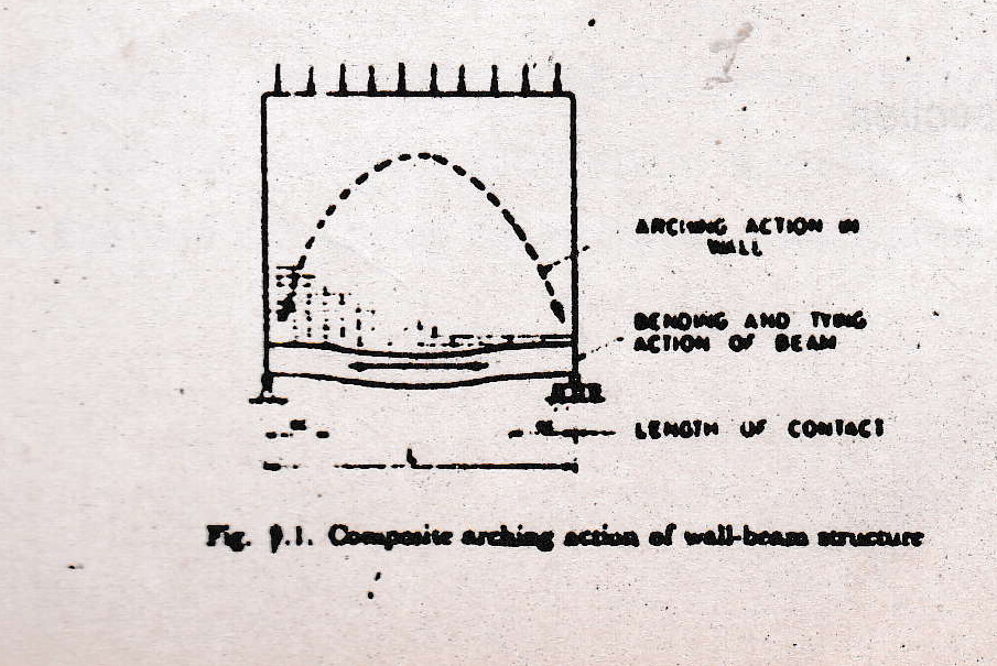
Beams are provided to carry masonry walls over openings such as doors, windows and as grade beams just above ground level in between piles. Such structures comprising beams am: the masonry above the called wall-beams. The behavior of wall-beam structures is more complex than the designer expects in general. The in-plane rigidity of the wall makes to act as an arch, or devotee, spanning across the opening. Additional vertical loads on tire veal are not transmitted vertically down to the beam below but are carried towards the stiff ends of the beam. The composite action can be described to a tied arch, as shown • in Fig. 1.1 in which the wall servos as the arch and the beam as the tie which prevents the arch from spreading. Fig.1.1 also shows that the vertical load is not transmitted exactly at t~ie supports but over regions approaching the supports. If the beam is very flexible, this may cause separation of the beam from the wall in the middle region.
A uniformly distributed fort e& load applied to the top of wall will be realstributed by the arching action so that high vertical compressive stresses and horizontal shear seed in the bottom corners of the wall. The redistribution of vertical stresses beam causes the bending moment in the beam to be substantially less than if the load had been applied with uniform distribution.
1.3 ANALYSIS AND DESIGN OF WALL-BEAM STRUCTURES
The behavior of wall-beam structures has been in investigated since several years by investigators. Extensive work on wall-beams has been delineate him Building Res Establishment, U.K. by Wood, Bughouse and Simms [1-31. More recently, Stafford end Piridington have developed a rational simple design method for the design structures based on the non-linear stress analysis of such structures using finite e method [41. Since it is impossible to cover- all the aspects of research on way structures, this chapter covers only the approach that he’s been de e. e in the ‘area.
Two methods of design have been proposed by Wood [11. The equivalent bending moment factor method is empirical and based on test results. The moment arm method based on elastic analysis of homogeneous deep.
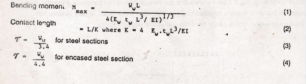
Wood recommended the depth of team to weigh 1/16 to 1/20 of span. Design bending moment of WL/50 is recommended for door and window openings near the supports of wails and a design bending moment of WL/100 for plain walls with door and window openings near the center, for freely supported a moment arm of 0.67 x depth of the wall with a limit of 0.70 times the span may be. Assumed. In case of continuous beams the limiting moment arm at the center is about the span and at the support is 0.34 times the span.Statford Smith and Riddington showed that the lengths of contact and the stress distribution between wall and beam are dependent on the relative stifistess of wall and beam. Relative stiffness was expressed by a dimensionless parameter based on beams on foundation, the following approximate formulae have been recommended for the des n of we-beam structures
It should be remembered that the reinforcement acts as a tie and consequentiy’ai. The reinforcements should be carried to the support to give adequate anchorage length past the edge of the supports. To sum up. due to composite action of wall over beams, the internal lever arm gets increased and then the actual moment is much reduced. the been: is more or less in axial tension. The vertical stress at supports increases due to arching shear stresses are to be carried by the wall. For composite action to develop between the wait and its support beam. horizontal shear must be transferred at the interface. Consideretiet. of composite action is of importance for economy as well as closer approximation is the actual behaviour of structure.
Reinforced brickwork linteis/beams were designed using composite behaviou: :, the Structurai Engineering Centre, Madras and both laboratory and field tests have proved their satisfactory behaviour (Plate 1.1).
1.4 INFILLED FRAMES
When a structural frame is infilled with a masonry wall, the diaphragm action of the wall leads to a substantial increase in the stiffness of the unit. The behaviour of the ”rents changes such that its members are subject to predominantly axial forces instead of beading forces. Although infilled frames can provide the most efficient means of resisting lateral loading, this structural property is generally not utilised. This is mainly due to the fact that no method of design has been fully developed and ever been recognised in the Codes of Practice.
1.5 METHODS OF ANALYSIS AND DESIGN OF INFILLED FRAMES
Available analysis and design methods for the strength and stiffness of infilled frames can be classified into thc methods basedcn the following:
1. The concept of elementary strength of materials treating the wall to act compositeiy with frame;
2. The concept of equivalent strut:
3. The finite element analysis;
4. The results of experimental investigations, – and
5. Plasticity, and collapse design approach.A great deal of research has been carried out in the area of infilled frames during the last several years. However the available information is inadequate to recommend a standard design method in the various codes of practice. The behavior of the infilled frames is evidenced in many recent earthquakes. The reinforced concrete columns bounded by nonstructural wall with openings become ‘ceptivn columns” and attract more shear til – m; Recent reeearclt on the seismic resistance oi thrilled trainee indicate that arm and the infill are to be designed carefully to develop high energy dissipation and ductiflty under seismic loads. in the fioviet Union, construction; of lramed buildings with brickwork infill over six storeys high in seismic areas is, as a rule, not practiced {10}.”in“ building regulations recommend the provision of dowels between columns and lniili 3hPlC5r’Jt its height in both seismic and non-seismic areas. it the length oi the infill is greetet than. 3 m, it should be connected to the uper beam with dowels at about if; m to 2 m part.
there is no doubt that the intiiis contribute to the strength and stiflnesss of the surrounding frames.- to ensure this contribution dependable, a tight fit construction of the iniili or provision oi sheer connectors is recommended. The strength and stillness of such engineered inliited frames without openings along the degonal to lateral wind loads can be approximately (zieierniined by the formulae given earlier. The frame and the lniili are to be designed adequately to otter composite resistance to seismic loads. An aceptabie method of design at initialed frames for seismic loads is yet to be developed.
1.8. REFERENCES
1. Wood, RH, “Studies in Composite Construction, Part l. The composite action of brick neneis supported on reinforced concrete beams“, National Building Studies Research Paper No.13, i952.
2. Burnouee, R. “Composite action between brick panel walls and their suporting beams”, itrcceedings oi the institution of Civil Engineers, June 1969.
3. since. Fini-i and LG. SW“ “A tentative design method tor the composite action of heavily loaded brick panel walls supported on reintorccd concrete beams”, Building fieseerchStation Current Paper 26/69, July 1989.
4. Siatterd Smith. 8. and JR Riddington. “The composite behaviour of elastic wail-beam system”, Proceedings of the institution of Civil Engineers, Vol. 63, June 1977. pp.377 393.
5. Pcivahow, S.V.. “Some investigations of the problems of the strength oi elements of buildings subjected to horizontal loading”, Tall Buildings, Pergamon Press Ltd, London, teat 5.2;},421-434.
6. Holmes, M, “Steel trames with brickwork and concrete iniilling“, Proceedings oi the institution oi Civil Engineers. 1961, pp.473-478.
7. Stafford Smith, 8., “Lateral stiffness ct inlilled trames‘, American Society of :1:neers, Structural Division, ST6, 1962, pp. 183-197.
8. Mainstone, R.J., ‘On the silliness and strength of infiiiea treaties Institution of Civil Engineers, London, Feb. 1971, pp. 57-90.
9. Riddington, JR, and B. Stafiord Smith, “Analysis of infllled frames estates with design recommendations’, Structural Engineers, Vol. 55, June 1989.
10. Polyakov. S.V.. ‘Design of earthquake resistant structures“, Translated in e
the Russian, Mir Publishers, Moscow, 1974.NOTATION
E – Elastic modulus of beam
EW – Elastic modulus of wall
H – Lateral load on the Infilied frame
h – _ Height of infill
l – Moment of inertia of beam
K – Dimension parameter to express relative stitness
L – Span of beam
lw – Length of infill
T – Axial tension in the beam
tw – Thickness of infill
Ww – Load due to weight oi wall plus super load
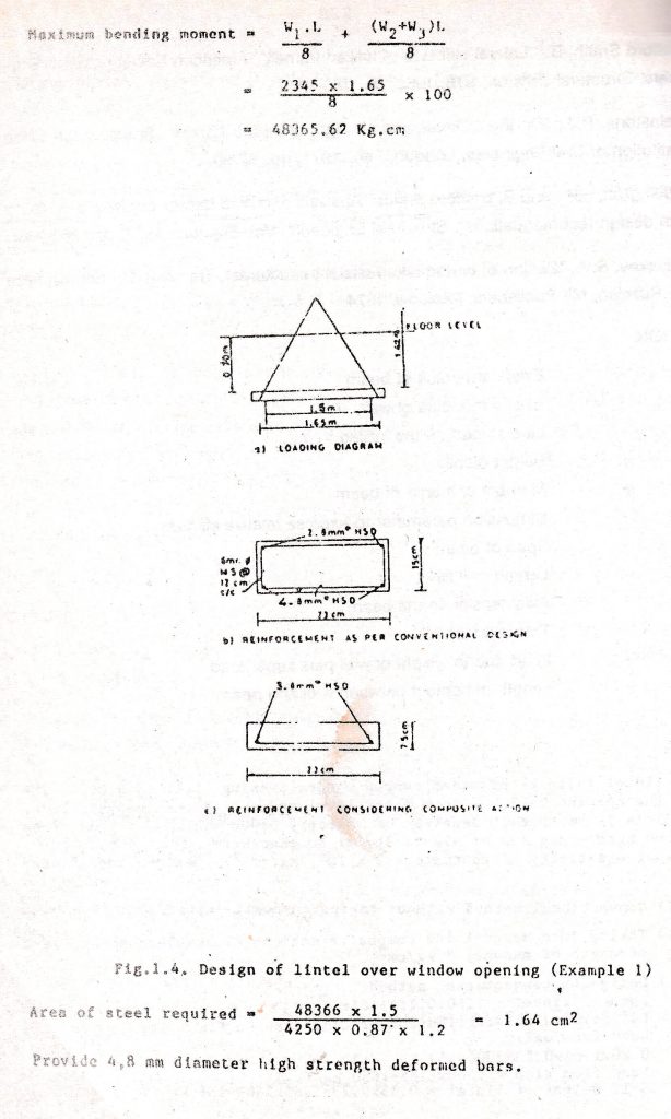
at – Length of contact between v all and beamEXAMPLE:
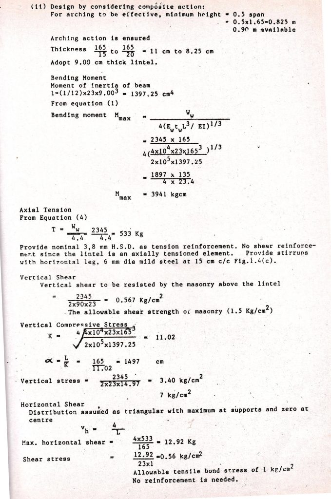
A lintel is to be provided over a window opening 1.5 m wide. Fhe top of the opening is 2.0 m from floor level and the floor height 3‘0“. The wall is 23 cm thick. Density of masonry 2000 Kg/m3. Load frg slab-1000 kg/m. Modulus of elasticity of brickwork2 = 4 x 10⁹ kg/em . Modulus of elasticity of concrete – 2 x 10⁵ kg/cm2. Design the lintel by:
(1) Conventional method without taking composite action.
(ii) Taking into account the composite action; Allowable compressive strength of masonry 7 kg/cm.
(i) Design by conventional method:
Span of lintel – 1.50+O.15-1.65m
60° triangular distribution of load assumed Fig.1.4 (a) Load from wall
0. 20×1. 65×0. 23×2000-559 kg (V1)
Load from slab = 1000×1.65-l650 kg(
Self-weight of lintel =- .15xo. 23×1 63x21i00= 136 Kg (:13)